

When we left off from the last update, I had successfully relocated the alternator and had the crank pulley machined down to one single groove, with a smaller belt fitted to suit. I was now ready to get back to the original task at hand; fitting the intercooler, radiator, and modifying the intake manifold.
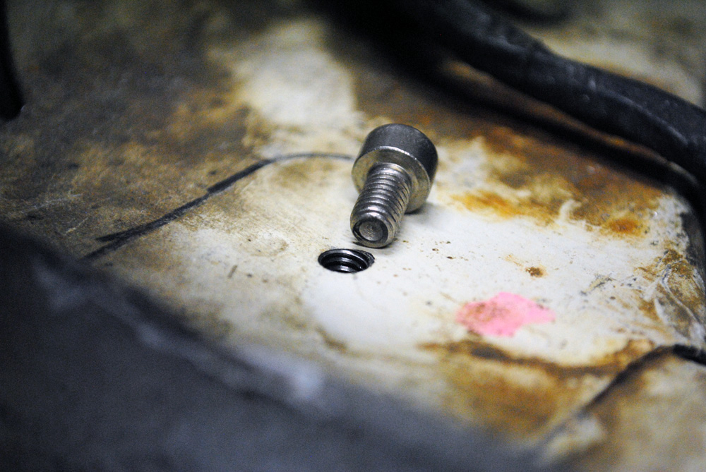
Now that I could fit the radiator in and intercooler in the bay without hitting the pulley, it was time to affix the lower mounting plate. The Datsport instructions told me to drill and tap 3 holes per side and use the supplied cap-head screws.
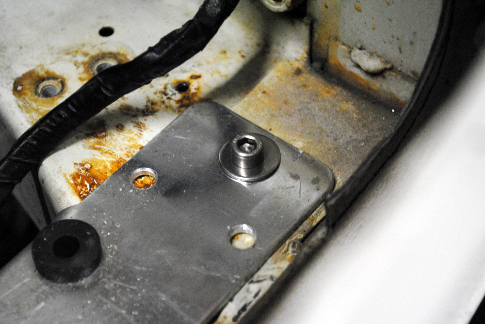
I chose to just do one on each side to start with, in case things changed. This ended up being a big help, as I had to move everything across a few mm, so I slotted the holes in the mounting plate to give me some wriggle-room.
The top mounts of the radiator slot onto the supplied cotton-reel bolts.
A couple of holes drilled into the front fascia did the trick and saw them firmly mounted.
It’s a bit hard to tell in this picture, but the intercooler that I bought with aftermarket outlets didn’t fit around my radiator. Both of the inlets just touched the radiator, but even if they were a few mm wider and just cleared the problem would be magnified once the radiator was brought closer due to the radius of the bends.
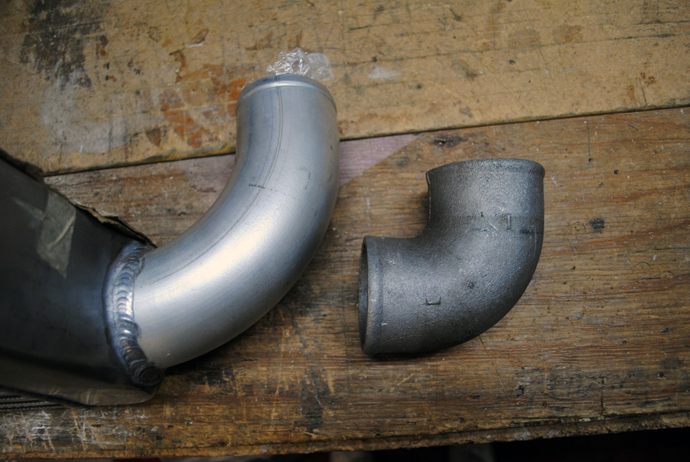
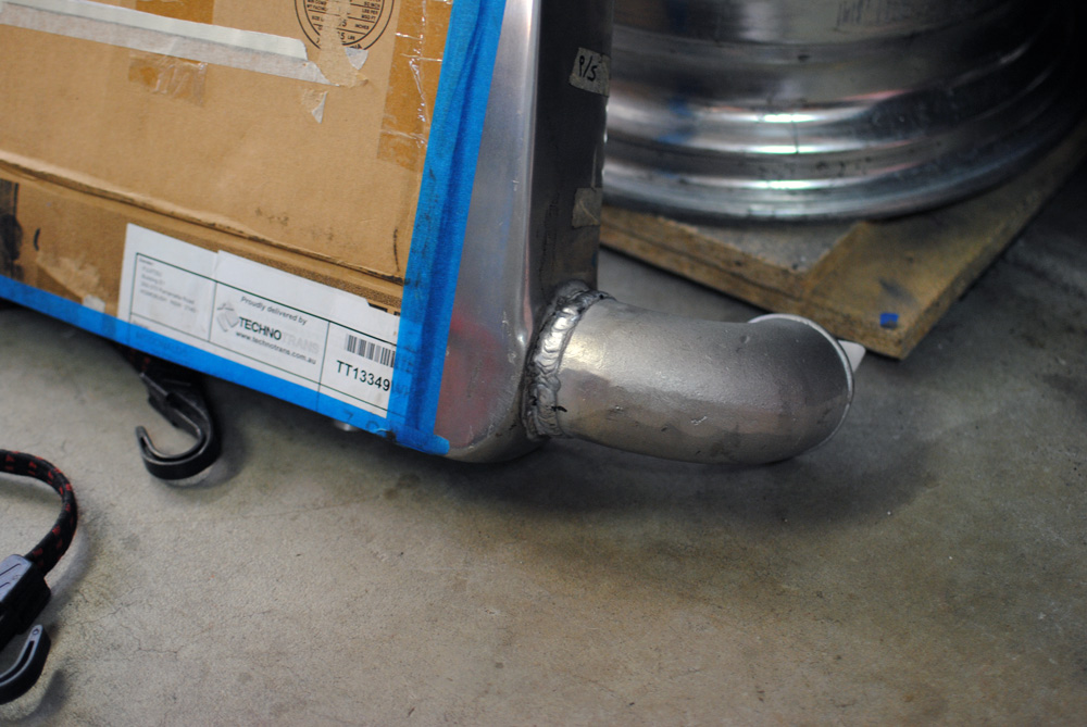
To rectify this I needed to remove the existing bends and weld on some new ones with a tighter radius.
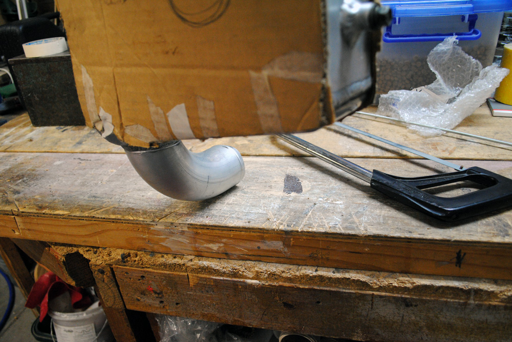
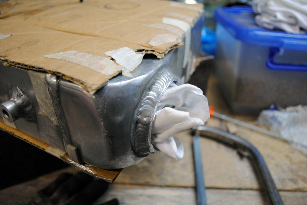
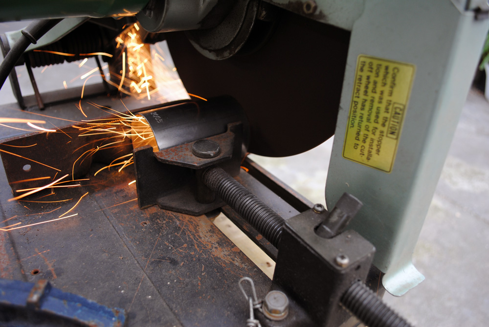
When it came time to do the cutting, I chose to do it by hand with a hacksaw, holding the cooler on it’s side with a rag stuffed down the outlets. This was all to try and reduce the amount of filings that could find their way into the core. I also took a die grinder with a cutting disc and cut a small groove around where I wanted to cut, so the hacksaw blade would have a good way to locate itself and wouldn’t walk around on me.
Cut off…
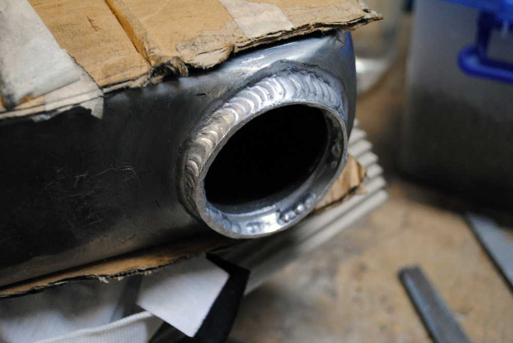
Nice and clean. As an extra precaution, once I’d finished cutting I stuck a vacuum cleaner in there and cleaned up any possible stray debris.
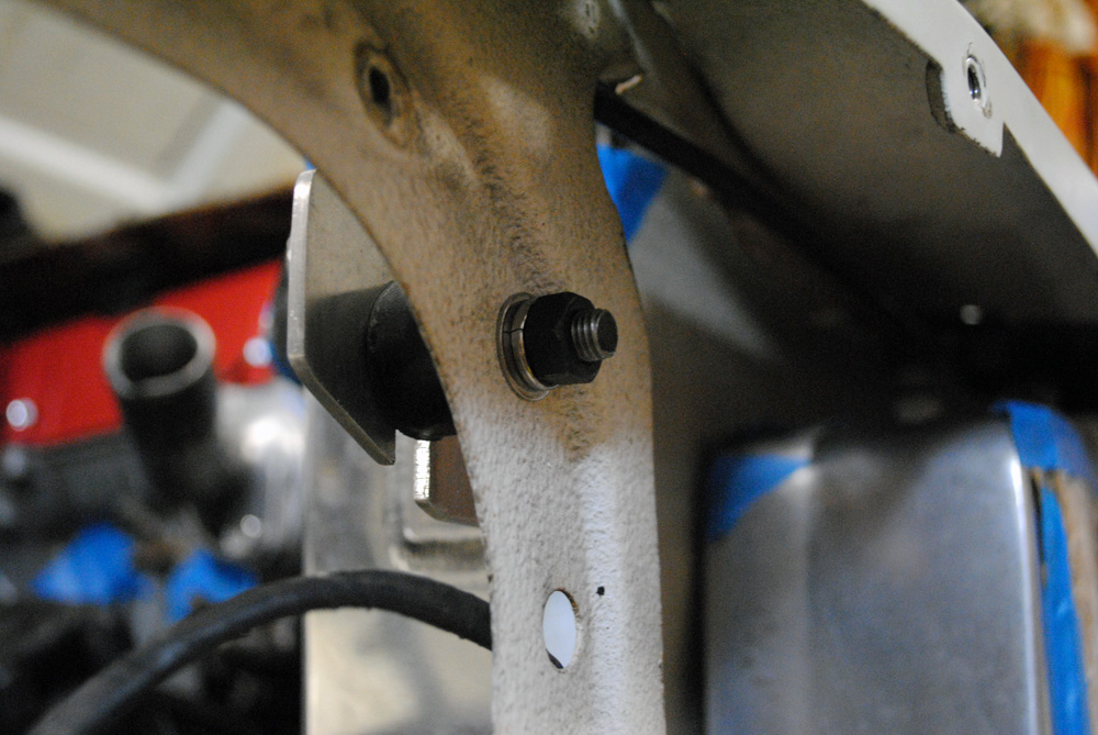
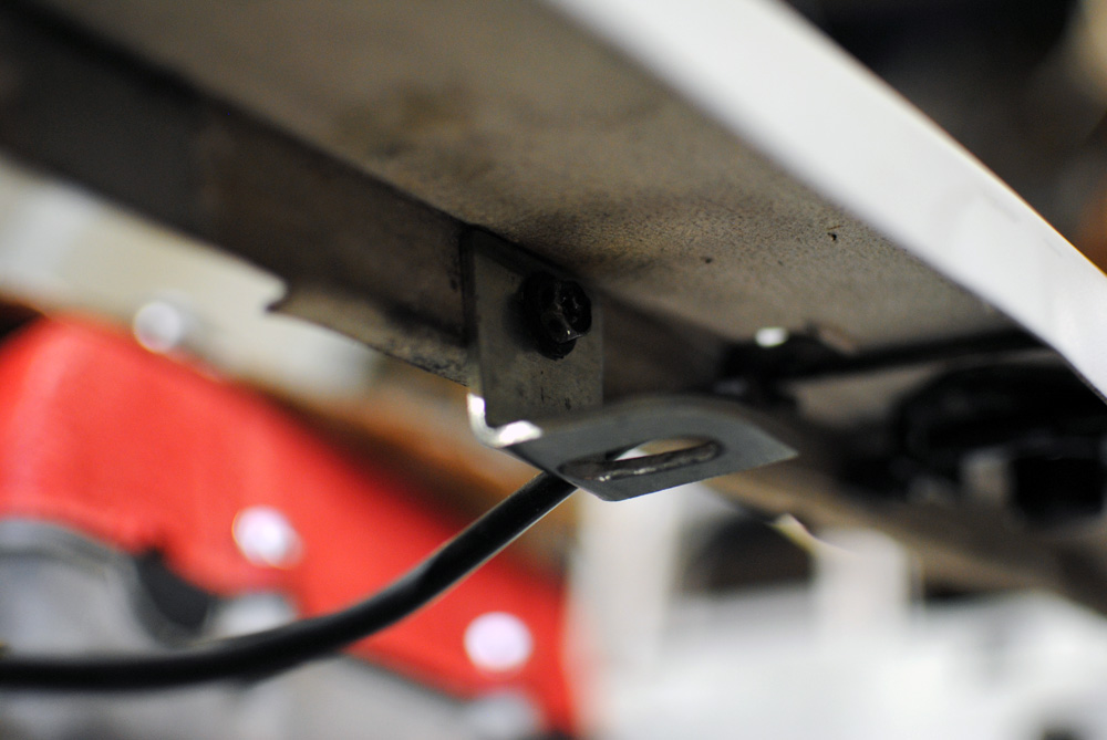
For upper intercooler mounts, I found some aluminium brackets that already had a right angle bend, and cut them down to shape. Once it was bolted into the cooler, I marked a hole on the radiator support and drilled it out.
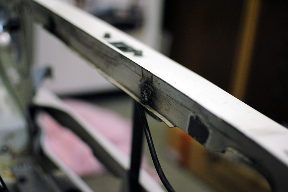
Instead of having a nut and bolt setup, I welded nuts to the back of the radiator support to make it easier for me to bolt the brackets in.
Done.
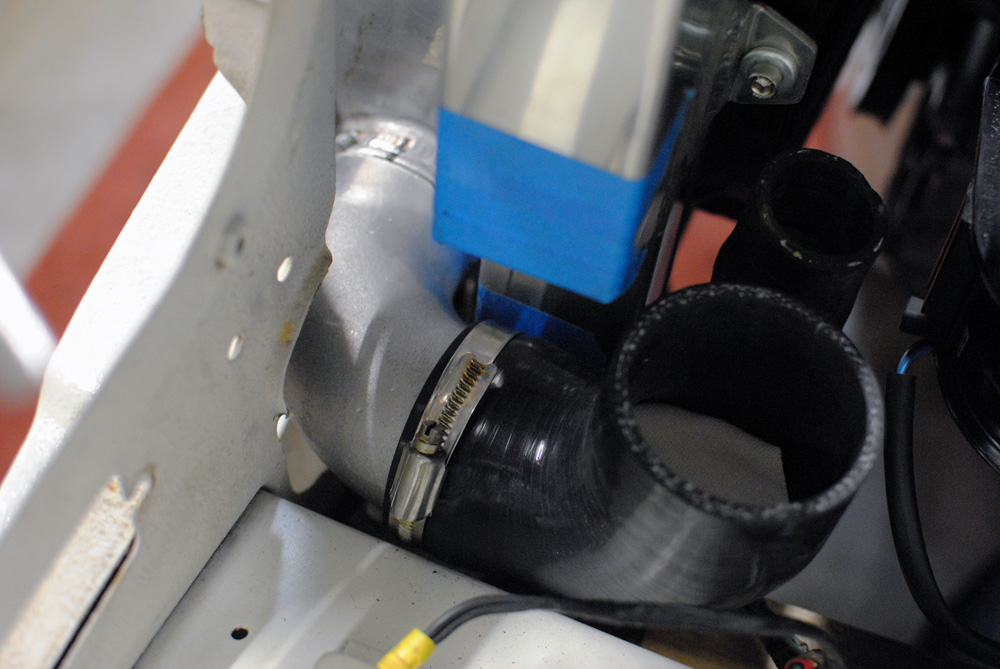
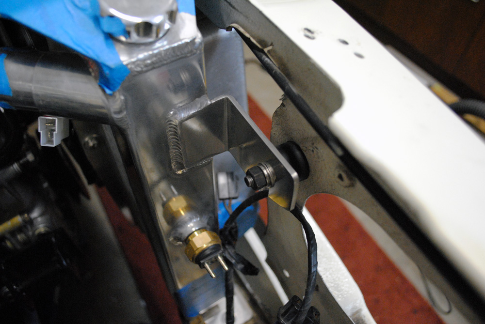
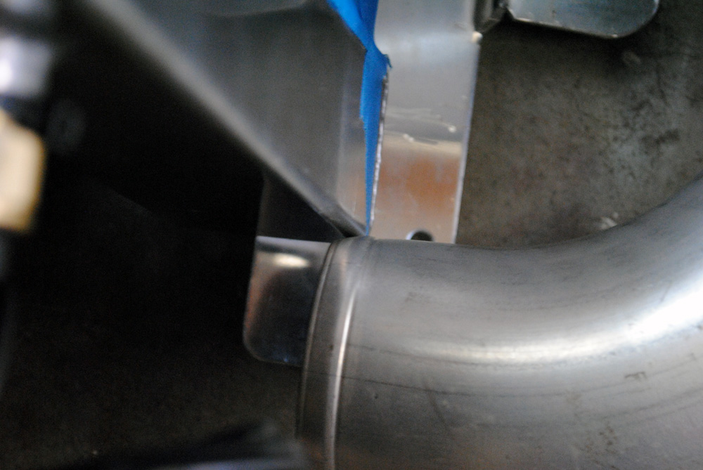
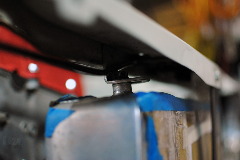
With both the radiator and intercooler bolted into place I was then able to mock up the position of the new sharp-radius intercooler outlets. Once I was happy with where they sat I marked them with a texta and took it all to my ever-patient mechanics at Protek Automotive to tack weld into place, as my mig welder cannot weld aluminium. You can see just how tight everything is, there’s only a few mm of clearance between the chassis rails, silicone hoses, and radiator, and that’s on both sides!
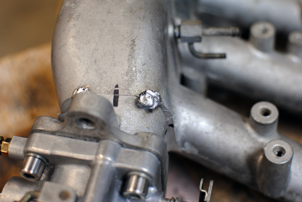
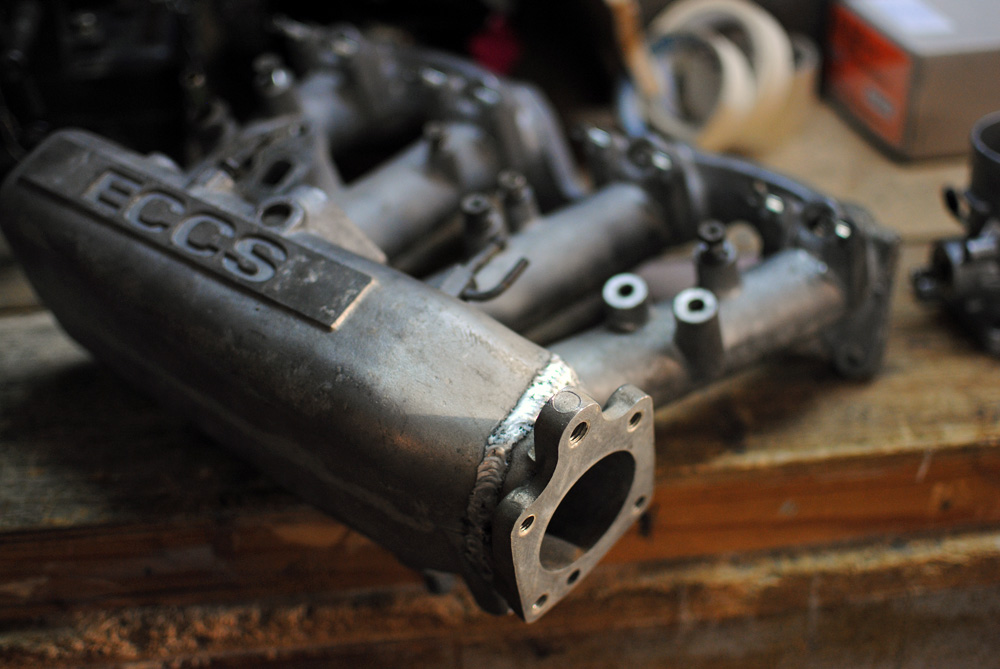
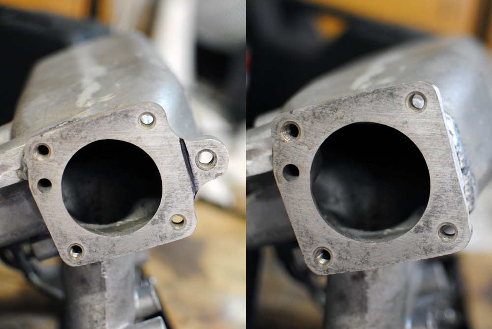
Another part I had tack welded was the intake manifold. You can see the line where it was cut, this was something I left to my mechanics as their angle grinder has a much bigger blade than mine so they were able to make a more precise and cleaner cut. To change the angle of the throttle body we actually made a single cut and then flipped the flange 180 degrees before re-welding it.
With the intake manifold flange and the intercooler outlets all tacked into place, I was could then make a start on mocking up my intercooler piping. I bought some 2.5″ straight pipe and some mandrel bends to mix and match.
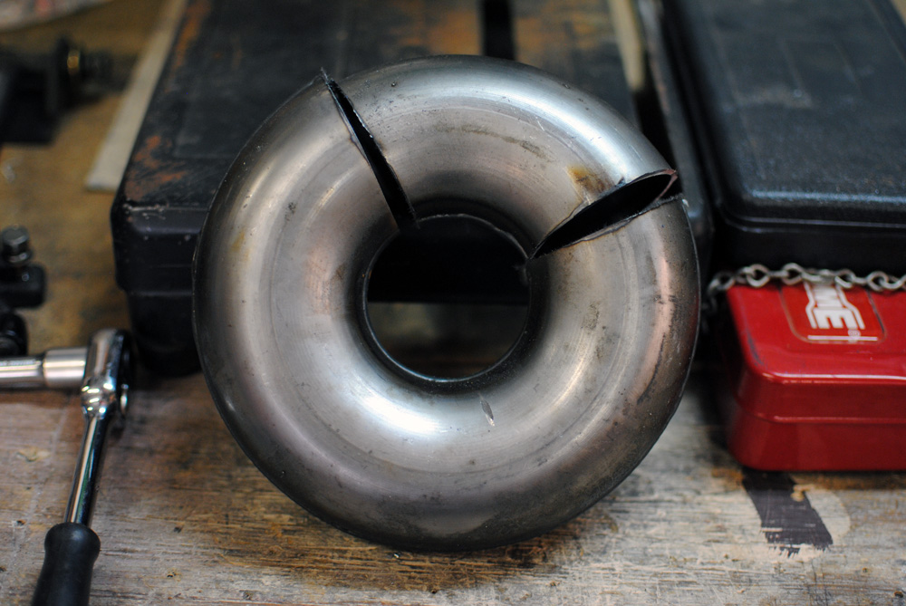
The cooler piping was another part of this round of mods that I did multiple times. The first time I did it I tried to fully weld them myself on the mig welder, but no matter what I did I kept getting pin-hole leaks in the joins. To test for leaks I filled the pipes with water. Also my cold-side pipe needed a tighter bend than I initially thought, so I bought the above “donut”. This series of pictures is my second attempt at piping.
This is the shape of the cold-side pipe, very simple.
Test fitted to the car. I got lucky with this side, very easy.
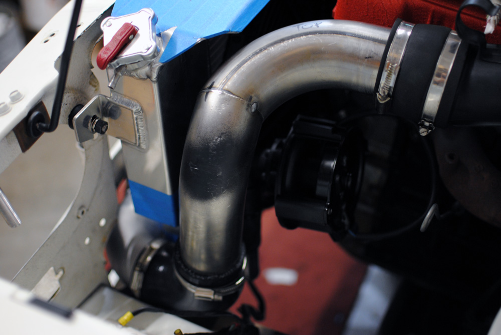
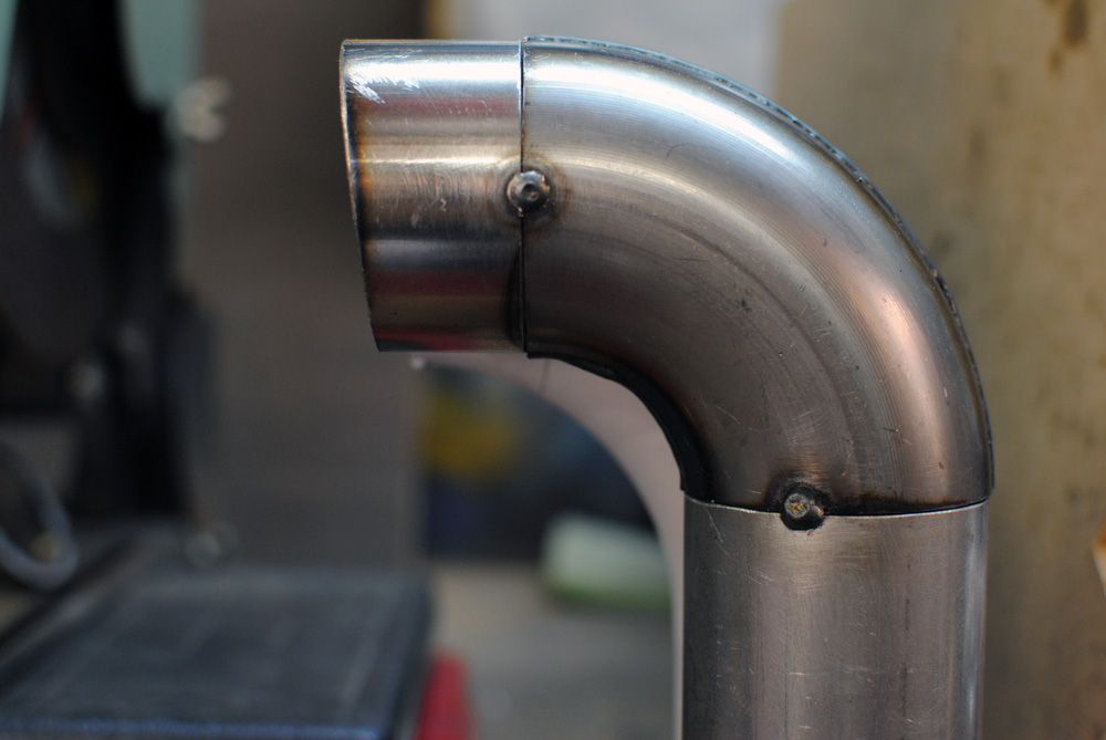
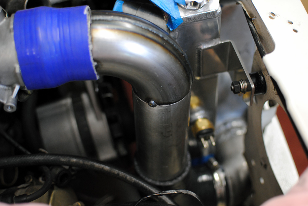
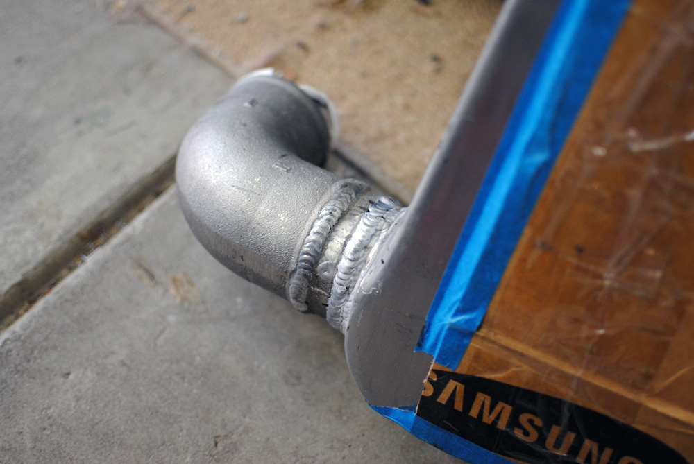
The hot-side was a bit more complicated, using two bends and some straight sections. At the top right of this image the piping joins into the factory piping. I did this to keep things looking as factory as possible and to also make the job easier for myself, instead of making all-new hot side piping. You can see the electric water pump hiding underneath the piping.
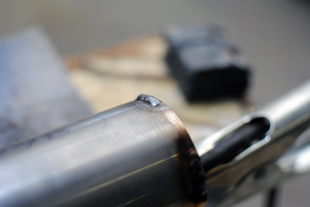
On the ends of both of the pipes I added a few series of tacks to stop the silicone hoses blowing off under pressure.
Once I was happy with the position of everything, I dropped it all off at Protek again for final welding.
One side was offset compared to the other.
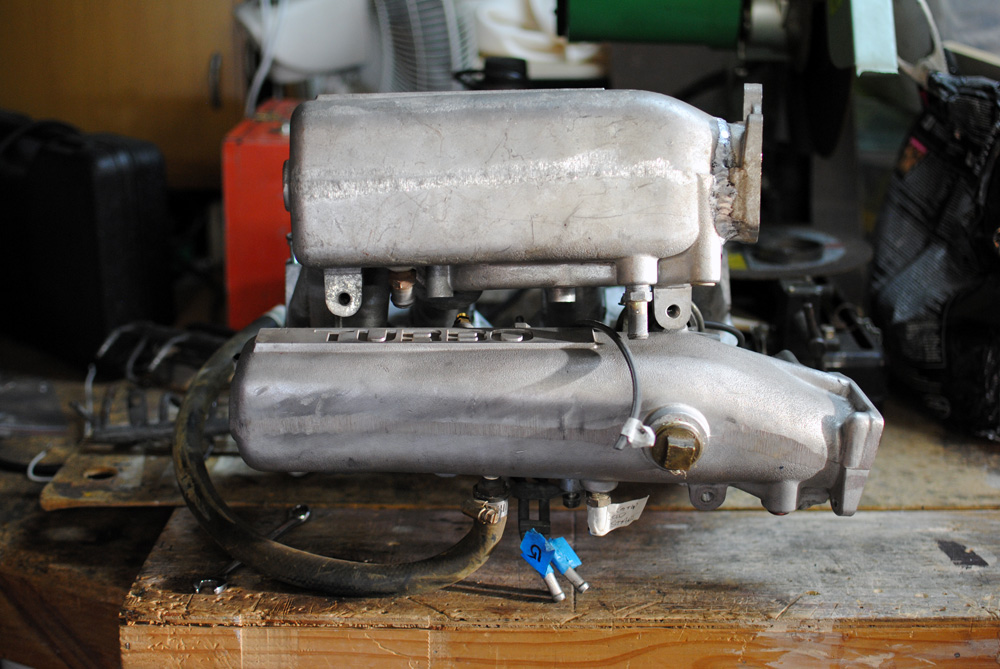
This shot shows the difference in size between the DR30 manifold (bottom) and S12 manifold (top). The runners are also shorter, but it was a bit hard to show that in a photo.
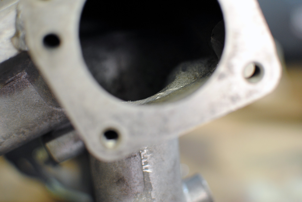
Since we had cut and rotated the throttle body flange 180 degrees, some things didn’t line up very well on the inside and wouldn’t do the airflow any favours.
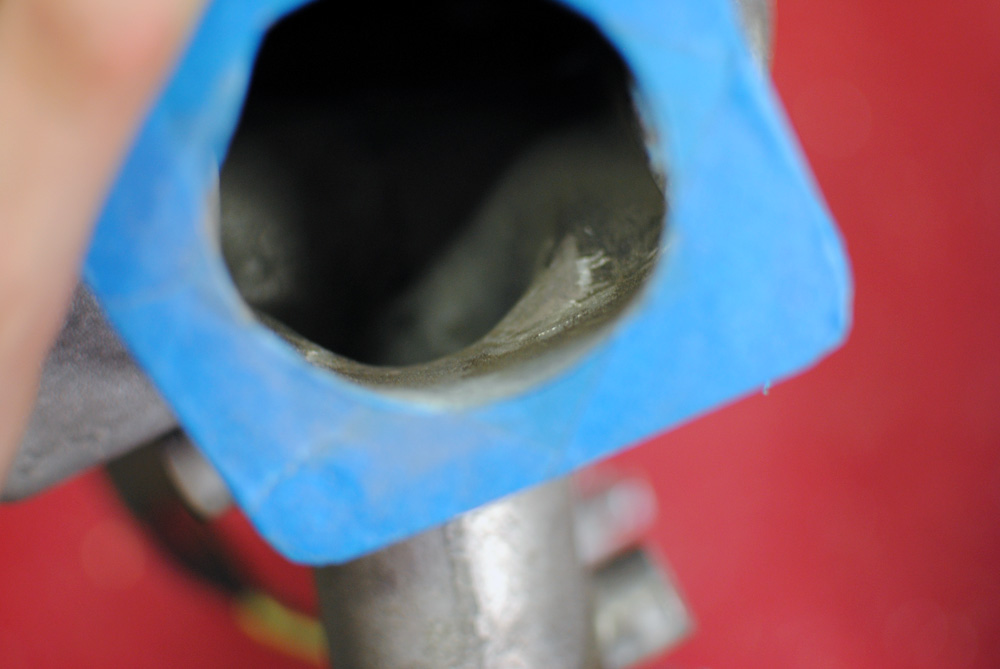
A bit of effort on the die grinder had it smoothed out. I lost count of how many aluminium splinters I got stuck in my fingers over the past few months.
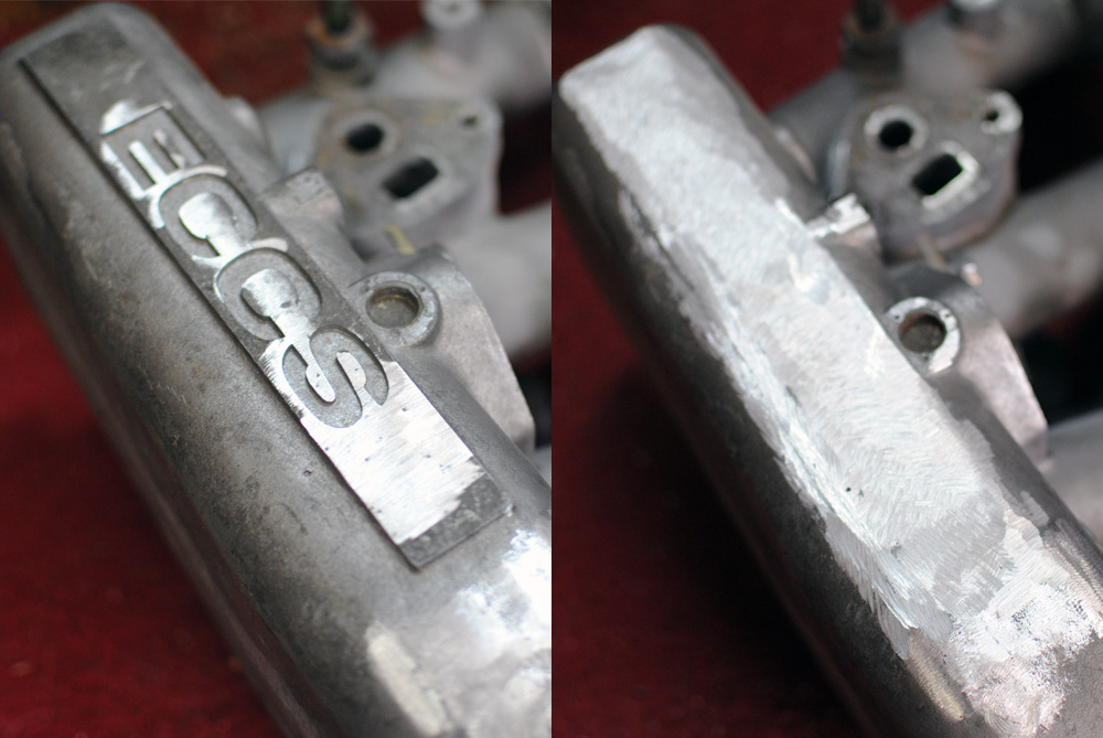
Another part of the manifold that was smoothed was the ECCS logo on the plenum.
Some more un-needed metal was a mounting tab that used to be underneath the throttle body, but was now above it.
I found out the hard way that there was a few minor differences between the DR30 and S12 manifolds, that being the fuel rail and the fuel pressure regulator. I don’t have any pictures of these until later in the piece but they were sourced the same way I bought the manifold, through the always-helpful members of the FJ20 Facebook page.
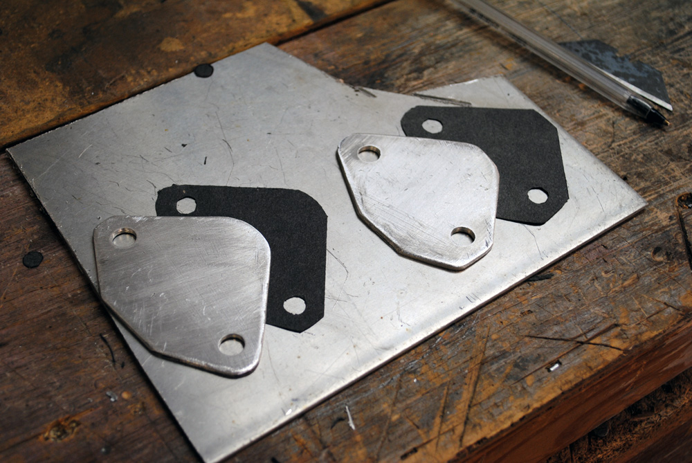
Still on the intake manifold, I made a couple of block-off plates and gaskets for some ports I won’t be using.

Speaking of gaskets, I also made new ones for the throttle body and thermostat. That sheet of gasket paper really came in handy.
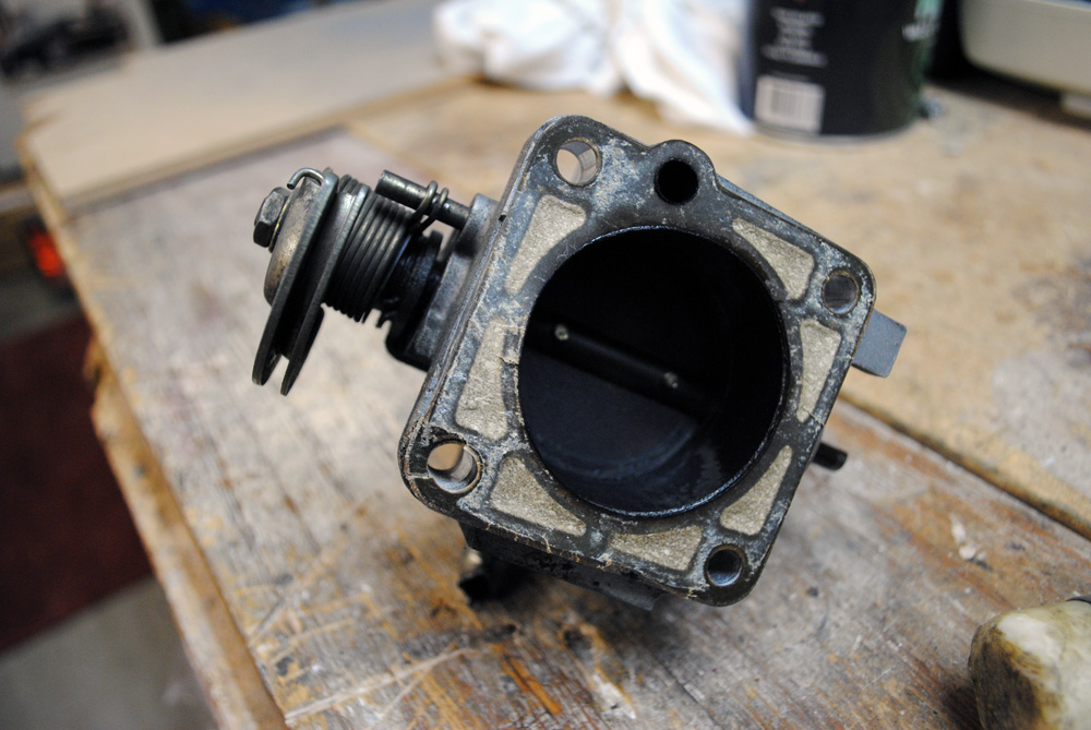
While we’re on the topic of the throttle body, I’ll start rounding out this post with the intense cleaning it received. First I removed it from the DR30 intake manifold, in it’s very black state.
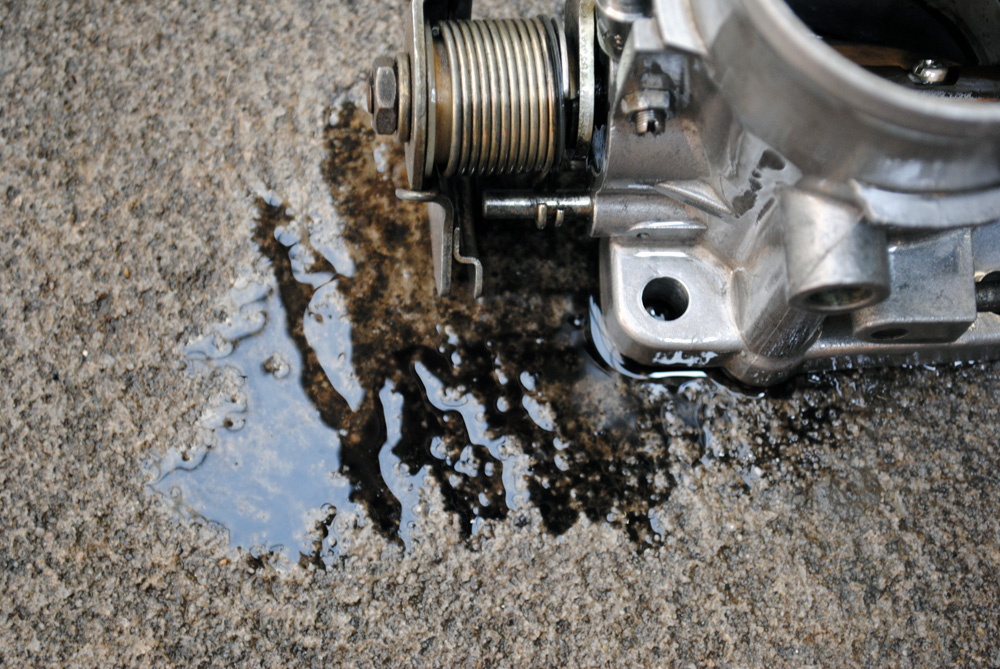
After removing the old gasket with a razor blade, I started spraying every nook and cranny with carby cleaner and degreaser…
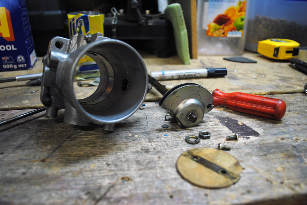
…until I finally bit the bullet and pulled the damn thing apart. This allowed me to clean it properly and also do a better job of painting it, which you’ll see later.
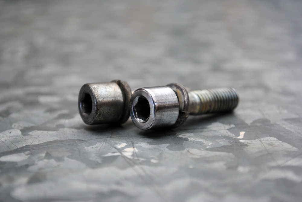
I was lucky in that the throttle body was already held on with stainless bolts, they just needed a quick sand and polish to bring back their shine.
That brings us to the end of part 2, but don’t worry, I’m already working on part 3, there’s plenty more to come.
To be continued…
Love the updates on your car! I can’t seem to recall, what’s your daily driver?
Really making me wish I had a bigger garage and another vehicle to take my time with!
Thanks Dave! My daily is a MKIV Golf 2.0, it used to have coilovers and R32 reps but I put it back to stock a while back. I’m looking to sell it and get back into something Japanese.
Several really quality articles or content on this site, ended up saving to favorite. läs mera http://hrpedia.ru/index.php?title=Special:RecentChanges&feed=rss